|
|
||
|
|
|
|
|
|
||
RV Electrical System Schematics
|
|
|
|
|
|
Copyright © 2002-2017 John Mayer. All rights reserved. For reuse policy see Reuse Policy In this section I show some common wiring methods, detailed schematics, and address some of the things NOT to do. If you do not understand power issues do not attempt to do this work yourself. These designs are intended as examples - your actual design needs to take into account your needs and will likely differ from these. Nevertheless, implementing all or part of the preferred design should result in a good system for you.
The Preferred Design
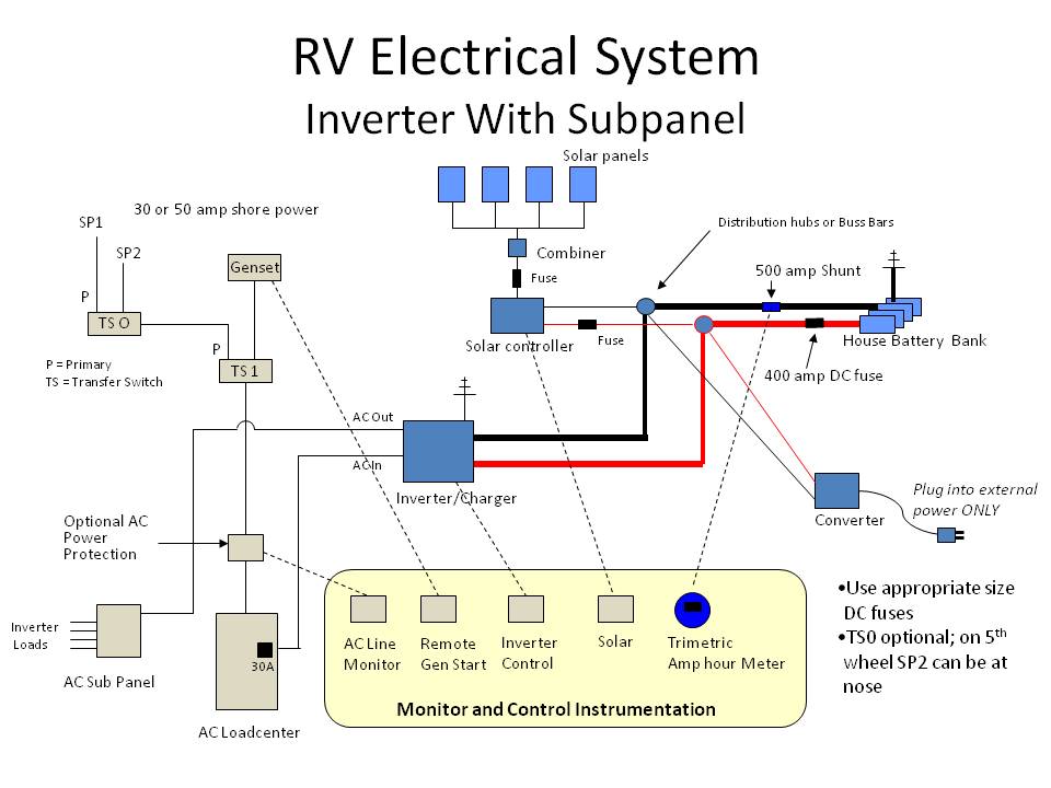
Electrical input sources include a genset (either a portable, an RV mounted or a truck mounted), and shore power sources. Optionally, two main shore power sources are shown, controlled by a separate 50-amp transfer switch (TSO). These are intended to provide for a shore connection at the front of the 5er, and at the rear of the 5er. The existing converter is shown connected to an external power source (other than the RV) for optional use. This should never be plugged into the RV, but only to an external source via an extension cord.
Two designs are shown. The first
is an inverter with a subpanel - typically used with a 50
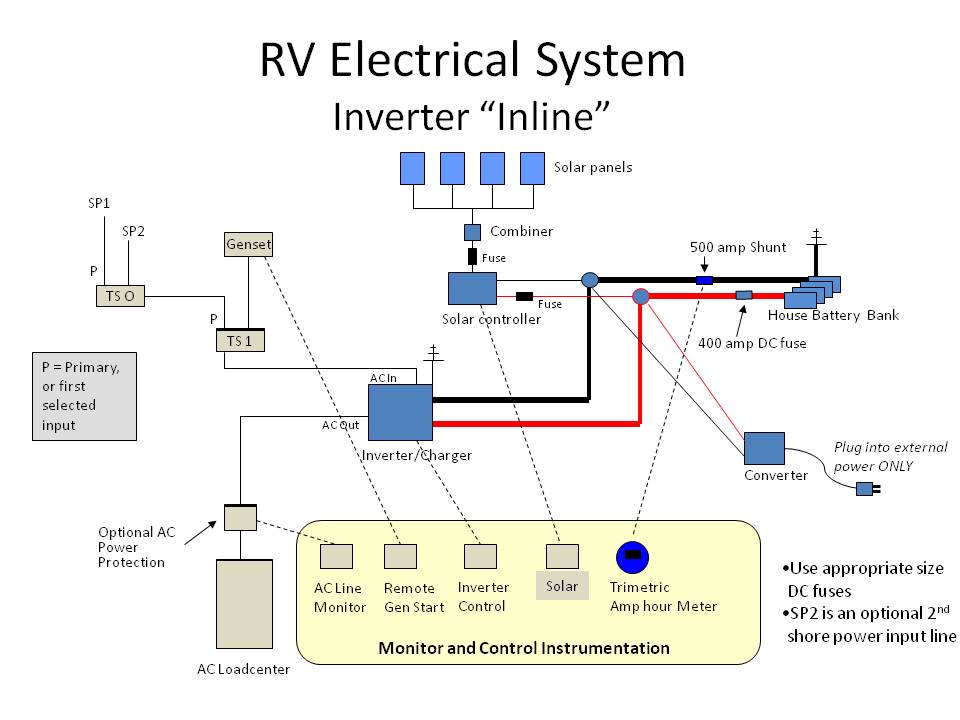
amp coach. The second is an inverter wired
inline to the loadcenter. While far easier to implement,
this is only applicable to a 30 amp RV - as discussed
elsewhere. Inverters on the market today do not provide for
passing through two legs of 50 amp power. Years ago, Xantrex
had an inverter - the RS3000 - that did have a 50 amp dual
leg transfer capability. This could be wired inline in a 50
amp RV. But this inverter is no longer manufactured.
Do not be confused by Magnum inverters that have "60 amp
transfer switches". This is a total of 60 amps, either on a
single input and/or output line, or on dual input/output
lines with 30 amps on each line. This is less than the 50
amps per line that is required for a 50 amp RV.
The shunt is a 500-amp shunt. It must be placed "downstream" of all loads to get an accurate measure of amps/amp hours. Place it between the distribution hub and the battery negative. Use appropriate size welding cable for the DC inverter runs. Consult the inverter installation instructions. Do not use less than 2/0. I prefer to use 4/0 in most situations if the inverter is 2000 watts or more. The inverter should not be more than 10 feet from the battery (cable run).
Optionally, I show two main shore power cables. When using an external generator (either portable or truck mounted) it is often convenient to have a shore power cable at the front of the rig. You simply use another 50-amp transfer switch - that way you can't have both "live" at once, or energize the other plug. This is obviously optional, but when wiring the transfer switches and deciding where to break into the main shore power cord you might consider leaving enough slack in the line to accommodate a future transfer switch if you decide not to do this right away.
Note 2
Distribution hubs are used for DC power connections. The
existing house DC wires that feed the DC loadcenter are not
shown in the drawing, but they should be moved to the
distribution hubs. Typically, a wire goes from the converter
directly to the battery, and another from the converter to the
DC loadcenter. If you are leaving the converter in place you can
remove the existing converter-to-battery wire, and splice a new wire
into the line that goes from the battery charger output of the
converter to the distribution hubs. (Your converter outputs may be
different, but you get the idea...) The reason not to attach
directly to the battery is that your battery monitor
shunt will not pick up the power added/consumed if you
bypass it. Loads must be upstream of the shunt. Not
between the shunt and the battery bank.
The solar input and conventional converter inputs attach
directly to the distribution hubs. You should attach all DC
power input/outputs here. Nothing should attach directly to the
battery except some of the instrumentation and monitoring lines,
and possibly the DC catastrophe fuse (if not in a holder). If
you have additional DC loads you are adding, you may want to add
a small DC fuse center, which would also attach to the
distribution hubs. I usually add one to support fusing for the
solar lines, and some of the instrumentation lines which
otherwise require inline fusing (which is not as neat, and not
centrally located).
Instrumentation
In the diagrams, the dotted lines denote instrumentation lines. These are not shown in detail - there are multiple connection points and lines for each instrument. Follow the instructions.
Sometimes the solar controller will have a remote display, and sometimes the entire controller will mount where the display can be seen - it depends on the controller you use. If you have a choice, acquire the remote monitor for the solar controller. It will make the wire run for the solar line shorter. The solar line should be as short as possible to minimize voltage drop. I prefer to use 4 gauge for the drop from the roof to the battery bank - but run the interactive calculators for your specific panels and distance. Sometimes that means you have to trim the wire where it goes into the terminals on the solar controller in order to make it fit. That is OK. On the roof, I interconnect the solar panels with a minimum of 10 gauge - which is what the typical MC4 lines are.
If the inverter monitor panel has a running amp hour capability (also called cumulative amp hour) then you can eliminate the Trimetric amp hour meter, since it would be redundant. If not, you really need to know your accumulated amp hours (either positive or negative), since that is the best measure of the state-of-charge of your battery bank. You can buy a Trimetric meter, with 500 amp shunt, for under $175 at www.solarseller.com. If you are using a Xantrex inverter, the LinkPRO or LInkLIte meters contain an amp hour function. If you are using a Magnum inverter, then I prefer to add the Trimetric monitor instead of using the integrated BMK. Not only is it cheaper (slightly), but I think it functions better and is more accurate. The advantage of using the BMK is that it is integrated into the existing inverter control panel. |
|
|
|
||